Short answer: power and torque are linked by speed. A motor's rated power does not automatically guarantee it can supply the torque required at any reduced speed or under electrical limits. If the motor or its drive cannot produce the torque demanded at the current speed, the rotor will decelerate even though the nominal motor power rating (kW) exceeds the instantaneous load (kW).
Key reasons explained
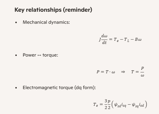
- Power vs torque relationship. Mechanical power is the product of torque and angular speed:
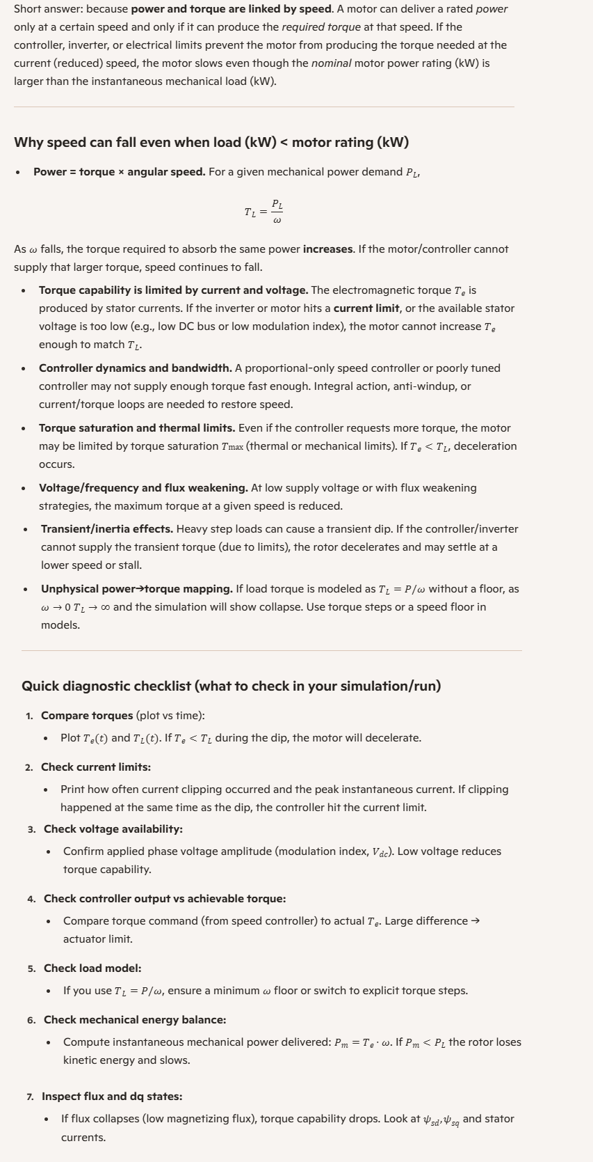
P = T · ω. For a fixed power demandP, the required torque isT = P / ω. As speedωfalls, the torque required to absorb the same power increases. - Torque capability is limited by current and voltage.
Electromagnetic torque is produced by stator currents. If the inverter or motor hits a current limit, or the available stator voltage is insufficient (low DC bus or low modulation index), the motor cannot increase torque to match the rising torque demand as speed drops.
- Controller and bandwidth limits.
A simple proportional speed controller or a slow controller may not supply torque quickly enough. Cascaded current loops (FOC) and properly tuned PI controllers are typically required to track torque demands during fast transients.
- Torque saturation and thermal limits.
Even if the controller requests more torque, the motor may be limited by maximum safe torque (thermal or mechanical). If
T_e < T_Lthe rotor decelerates. - Modeling pitfalls: power→torque at low speed.
A load model that computes torque as
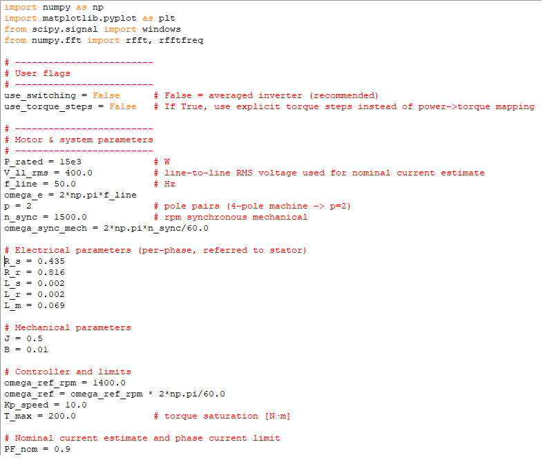
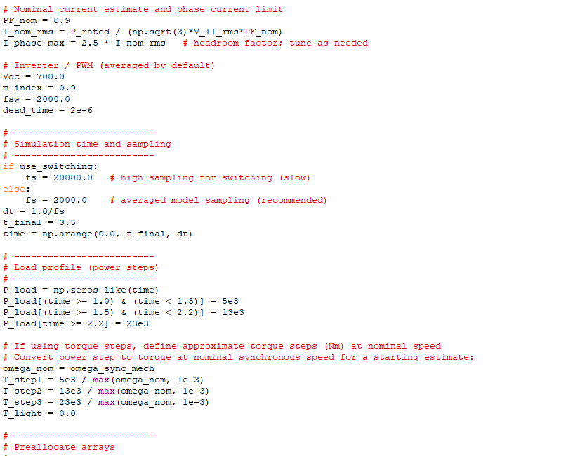
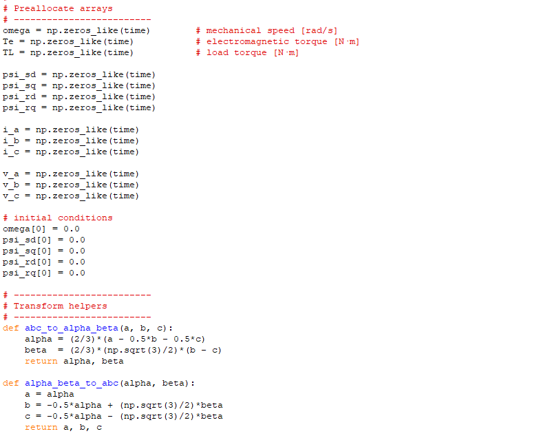
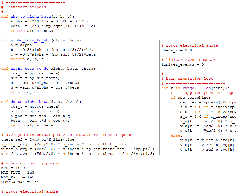
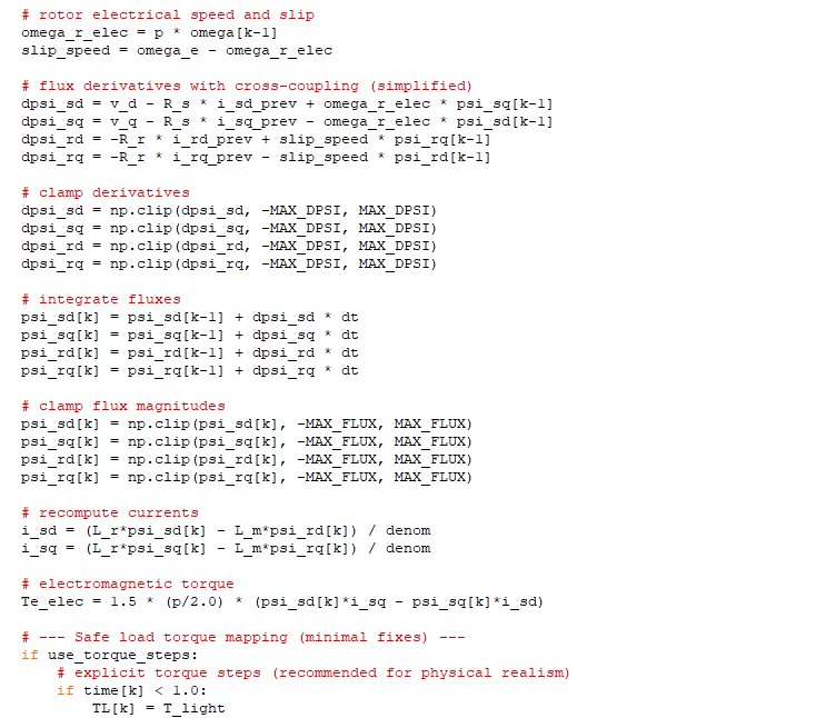
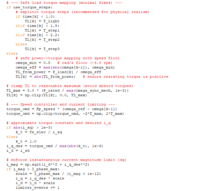
T_L = P_load / ωwithout a minimum speed floor is numerically and physically dangerous: as ω→0 the computed torque tends to infinity, causing collapse in simulation and unrealistic behavior in practice. Use explicit torque steps or a safe floor for ω in models. - Voltage/frequency and flux effects.
At low supply voltage or under flux weakening, the maximum torque at a given speed is reduced. If the motor cannot produce the required torque within its voltage limits, speed will fall.
- Transient inertia and energy balance.
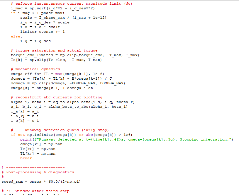
During a sudden load step the rotor's kinetic energy supplies the deficit. If the motor cannot replenish that energy (insufficient torque), the rotor slows until a new equilibrium is reached or until stall.
Practical diagnostics
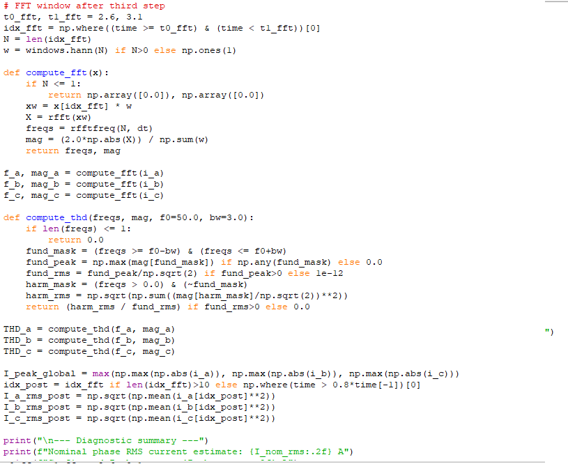
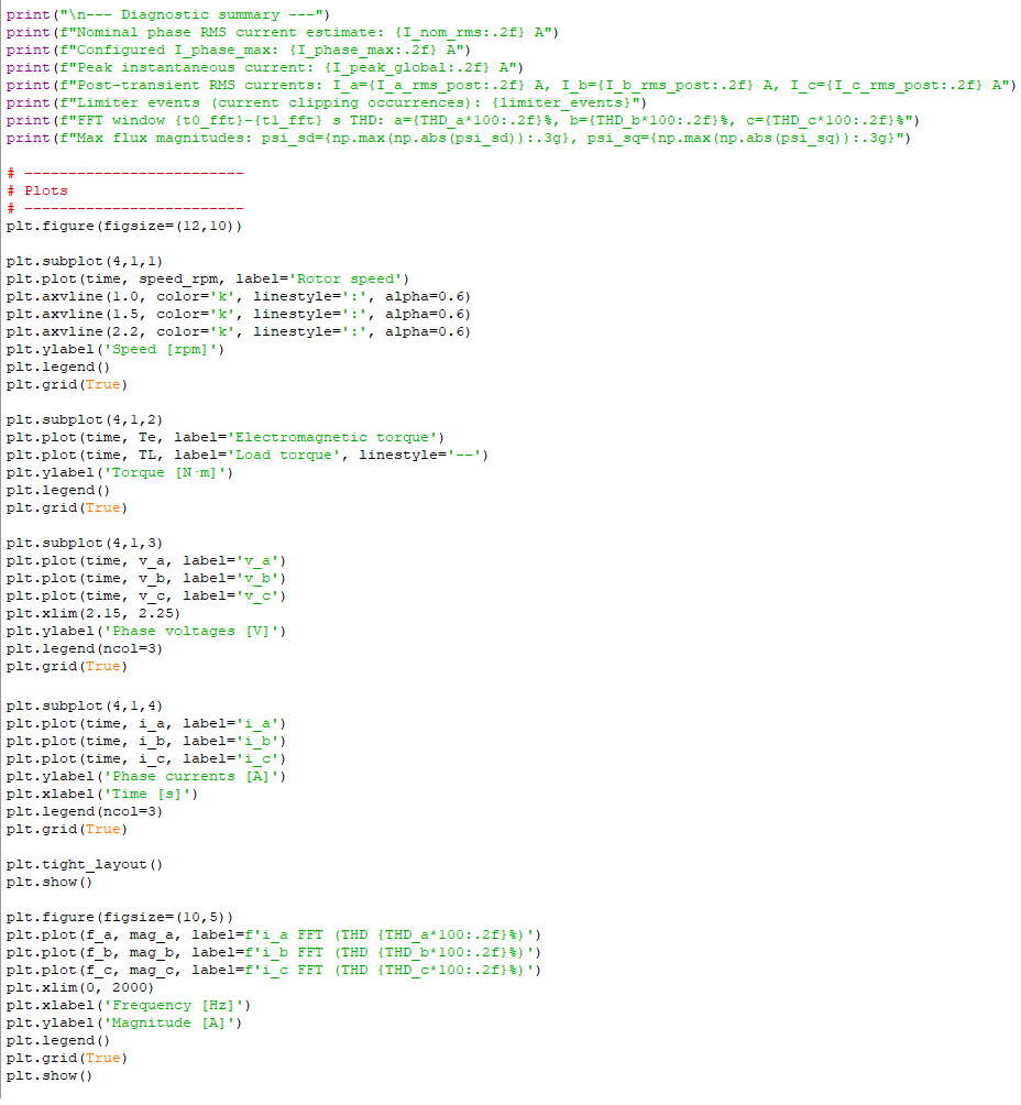
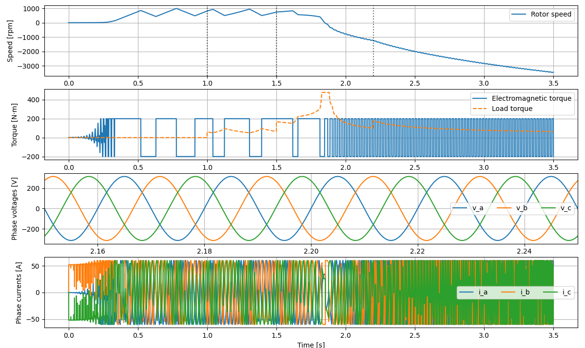
- Plot and compare
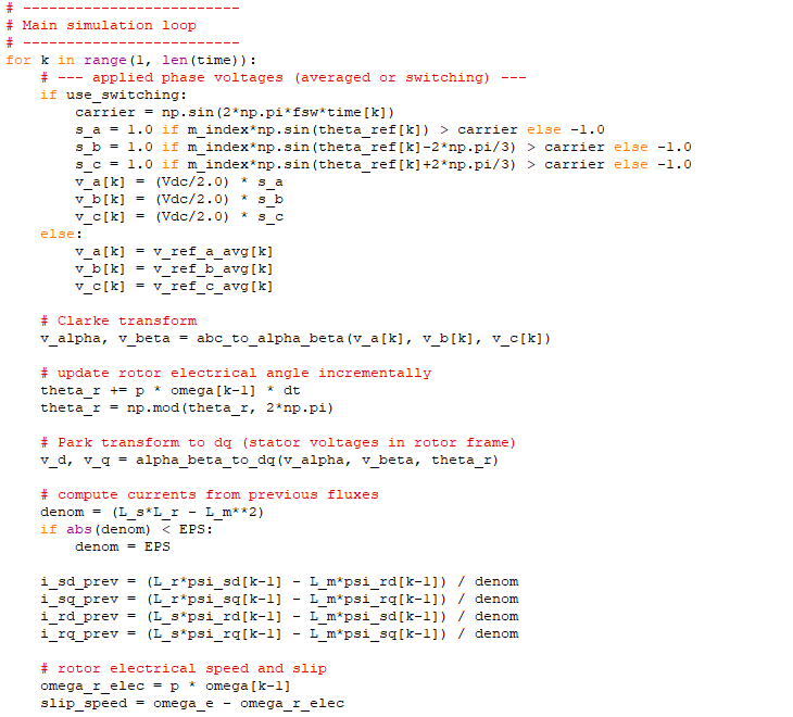
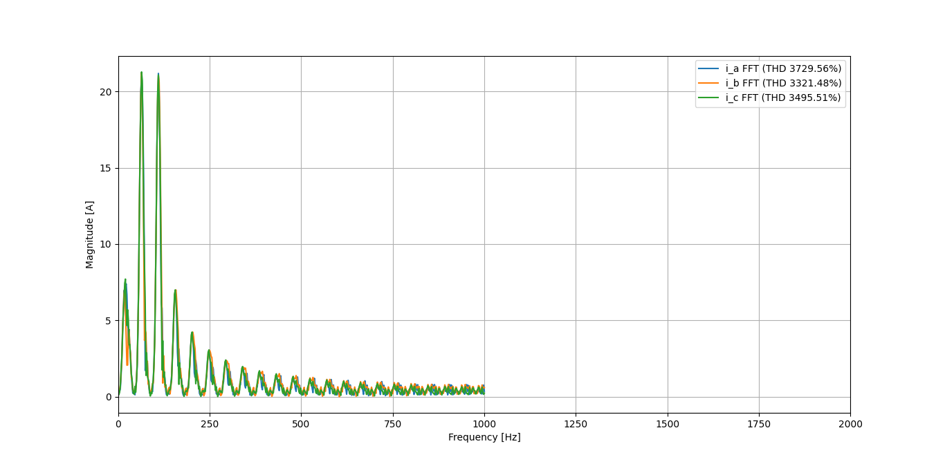
T_e(t)andT_L(t). IfT_e < T_Lat a load step, deceleration is expected. - Check current clipping and limiter events in the drive — frequent clipping at the time of speed dip indicates torque limitation.
- Compare instantaneous mechanical power
P_m = T_e · ωto the load powerP_L. IfP_m < P_Lthe rotor loses kinetic energy and slows. - Use a safe load model (torque steps or a power→torque mapping with a minimum speed floor) to avoid unphysical torque growth near zero speed.
Remedies and design choices
- Increase available torque: raise current limit (if safe), increase DC bus voltage or modulation index, or reduce load ramp rate.
- Improve control: add integral action or cascaded current PI loops (FOC) so torque is tracked quickly and robustly.
- Use torque-step load models for simulation, or apply a minimum speed floor when converting power to torque.
- Implement anti‑stall logic or staged load application to avoid sudden collapse.
Short checklist (what to inspect in a simulation or test)
- Is
T_eless thanT_Lduring the dip? If yes, speed will fall. - Did current limiting occur at the same time? If yes, the drive hit its torque-producing limit.
- Is the load modeled as
P/ωwithout a floor? If yes, replace with torque steps or add a floor. - Are applied voltages and modulation index sufficient to produce the required flux and torque?
References
- Copilot AI Think Deeper 2025
- Riccardo Marino · Patrizio Tomei · Cristiano M. Verrelli. Induction Motor Control Design. Springer‑Verlag London Limited, 2010. ISBN 978-1-84996-283-4.
Footnote: "The 3-phase Induction Motor, part 1"